
The hydraulic system is the heart of every forklift, providing the precise power and control necessary for lifting, tilting, and positioning loads safely and efficiently. This sophisticated system, operating at pressures that can exceed 2,500 PSI, requires meticulous maintenance to ensure reliable operation, prevent costly failures, and maintain workplace safety.
Hydraulic system failures account for approximately 30% of all forklift downtime, making proper maintenance critical for operational efficiency. A well-maintained hydraulic system not only prevents unexpected breakdowns but also optimizes fuel efficiency, extends component life, and ensures consistent lifting performance. Conversely, neglected hydraulic systems can lead to catastrophic failures, safety incidents, and repair costs that can exceed the value of the entire forklift.
This comprehensive guide explores the essential aspects of hydraulic system maintenance, from routine fluid monitoring to advanced troubleshooting techniques, providing maintenance professionals with the knowledge needed to keep these vital systems operating at peak performance.
Understanding Forklift Hydraulic Systems
Before diving into maintenance procedures, it’s essential to understand the basic components and operation of forklift hydraulic systems.
Primary System Components
A typical forklift hydraulic system consists of:
- Hydraulic reservoir: Stores hydraulic fluid and allows for thermal expansion
- Hydraulic pump: Creates system pressure, typically gear or piston type
- Lift cylinders: Provide the force for mast lifting operations
- Tilt cylinders: Control forward and backward fork tilt
- Control valve assemblies: Direct fluid flow to various functions
- Hydraulic hoses and fittings: Transport pressurized fluid throughout the system
- Filtration system: Maintains fluid cleanliness and system protection
- Pressure relief valves: Protect system components from over-pressurization
Operating Principles
Hydraulic systems operate on Pascal’s principle, where pressure applied to confined fluid is transmitted equally in all directions. In forklifts, this allows relatively small hydraulic pumps to generate enormous lifting forces through the use of different cylinder diameters and mechanical advantage.
The system operates in a continuous cycle: the pump draws fluid from the reservoir, pressurizes it, and sends it through control valves to the appropriate cylinders. When a function is activated, pressurized fluid enters one side of a cylinder while fluid from the other side returns to the reservoir, creating controlled movement.
Fluid Level Monitoring and Management
Proper hydraulic fluid management is the foundation of hydraulic system health.
Daily Fluid Level Checks
Consistent fluid level monitoring prevents the most common cause of hydraulic system failure—running low on fluid:
Pre-operational Inspection Process:
- Park the forklift on level ground with the mast fully lowered and tilted back to the upright position
- Allow the engine to cool for at least 30 minutes after operation to ensure accurate readings
- Clean the reservoir cap area to prevent contamination during inspection
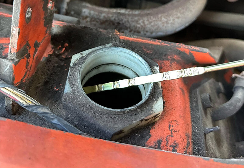
- Check the sight gauge or dipstick following manufacturer specifications for proper fluid level
- Document findings on the daily inspection checklist
Fluid Level Interpretation:
- Fluid should typically be between the “MIN” and “MAX” marks on the sight gauge
- Levels below minimum indicate potential leaks or excessive consumption
- Levels above maximum suggest overfilling, which can cause foaming and poor performance
- Gradual level decreases over time indicate normal consumption and minor internal leakage
Fluid Quality Assessment
Beyond quantity, fluid quality directly impacts system performance and longevity:
Visual Inspection Indicators:
- Color changes: Fresh hydraulic fluid is typically amber or light brown; dark, black, or milky fluid indicates contamination or degradation
- Consistency: Fluid should flow smoothly; thick, syrupy consistency suggests oxidation or thermal breakdown
- Particle contamination: Visible particles, metal flakes, or sediment indicate system wear or contamination
- Water contamination: Milky or foamy appearance suggests water intrusion, which can cause severe system damage
Advanced Fluid Analysis: For critical applications, periodic laboratory analysis can provide detailed information about:
- Viscosity changes indicating thermal or oxidative degradation
- Particle contamination levels and types
- Water content measurements
- Additive depletion analysis
- Wear metal analysis indicating component condition
Seal Replacement and Management
Hydraulic seals are critical components that maintain system pressure and prevent fluid leakage.
Understanding Seal Types and Functions
Different seal types serve specific functions within the hydraulic system:
Primary Seal Types:
- Rod seals: Prevent fluid leakage along cylinder rods during extension and retraction
- Piston seals: Maintain pressure separation between cylinder chambers
- Wiper seals: Remove contaminants from cylinder rods during retraction
- Static seals (O-rings): Seal stationary connections and prevent leakage at fittings
- Rotary seals: Seal rotating shafts in pumps and motors
Seal Failure Identification
Early identification of seal failure prevents minor leaks from becoming major problems:
External Leakage Signs:
- Visible fluid puddles beneath the forklift
- Wet spots on cylinder rods or hose connections
- Fluid buildup on the mast structure
- Reduced hydraulic fluid levels requiring frequent top-offs
Performance-Related Symptoms:
- Slow or jerky cylinder operation
- Inability to maintain lift height under load
- Excessive pump noise or cavitation
- Inconsistent lifting or tilting speeds
Seal Replacement Procedures
Preparation Phase:
- Relieve system pressure by operating all functions with the engine off
- Clean the work area thoroughly to prevent contamination
- Drain hydraulic fluid from the component being serviced
- Photograph connections before disassembly for reassembly reference
Disassembly Best Practices:
- Use proper lifting equipment for heavy components
- Mark hydraulic lines for correct reassembly
- Inspect all components for wear or damage during disassembly
- Clean all parts thoroughly before seal installation
Installation Guidelines:
- Use only manufacturer-specified seal materials and sizes
- Lubricate seals with clean hydraulic fluid during installation
- Inspect seal seats for scratches, nicks, or corrosion
- Use proper installation tools to prevent seal damage
- Ensure correct seal orientation and seating
Hose Inspection and Maintenance
Hydraulic hoses operate under extreme conditions and require regular inspection and proactive replacement.
Comprehensive Hose Inspection
Visual Inspection Checklist:
- External cover condition: Look for cuts, abrasions, weather checking, or exposure of reinforcement layers
- Coupling integrity: Check for corrosion, damage, or loose connections
- Hose routing: Verify proper support, adequate bend radius, and freedom from rubbing
- Leakage signs: Inspect for fluid seepage at fittings or along the hose length
Physical Inspection Techniques:
- Flexibility test: Gently flex the hose to check for stiffness or cracking
- Coupling tightness: Ensure all fittings are properly tightened to specification
- Support verification: Confirm that hose clamps and supports are secure and properly positioned
Hose Replacement Criteria
Immediate Replacement Indicators:
- Any visible wire reinforcement
- Fluid leakage at any point
- Coupling separation or damage
- Cuts or gouges deeper than 25% of hose wall thickness
- Severe weather checking or cover deterioration
Preventive Replacement Guidelines:
- Replace hoses approaching manufacturer-recommended service life (typically 4-6 years)
- Replace during major component overhauls even if not visibly damaged
- Consider replacement if repeatedly subjected to extreme operating conditions
- Replace entire hose assemblies rather than attempting field repairs
Proper Hose Installation
Installation Best Practices:
- Use only manufacturer-approved hose assemblies with proper pressure ratings
- Maintain minimum bend radius specifications to prevent premature failure
- Ensure adequate hose length to accommodate full cylinder travel
- Route hoses to minimize exposure to heat sources, sharp edges, and potential damage
- Install proper hose clamps and supports at recommended intervals
Pressure Testing and System Analysis
Regular pressure testing ensures system integrity and identifies potential problems before they cause failures.
Pressure Testing Equipment and Procedures
Required Equipment:
- Calibrated pressure gauge set with appropriate pressure range
- Test gauge connections compatible with system test ports
- Safety equipment including eye protection and hydraulic-rated gloves
Testing Procedure:
- Warm the system by operating all functions for several minutes
- Connect test gauges to designated test ports following manufacturer specifications
- Operate individual functions while monitoring pressure readings
- Compare readings to manufacturer specifications
- Document results and identify any deviations from normal operating parameters
Interpreting Pressure Test Results
Normal Operating Parameters:
- System pressure should reach specified maximum within manufacturer tolerances
- Pressure should build smoothly without excessive fluctuation
- Individual circuit pressures should match specifications for each function
Problem Indicators:
- Low maximum pressure: May indicate pump wear, pressure relief valve problems, or internal leakage
- Slow pressure buildup: Often indicates pump efficiency loss or significant internal leakage
- Pressure fluctuation: May suggest contamination, air in the system, or pump cavitation
- Uneven circuit pressures: Could indicate flow control valve problems or circuit restrictions
Contamination Prevention Strategies
Contamination is the leading cause of hydraulic system failure, making prevention critical for system longevity.
Sources of Contamination
Primary Contamination Sources:
- Built-in contamination: Manufacturing residues, assembly particles, and break-in wear
- Ingested contamination: Dirt, dust, and moisture entering through breathers and seals
- Generated contamination: Wear particles from normal system operation
- Maintenance-induced contamination: Contamination introduced during service procedures
Contamination Control Measures
Filtration System Maintenance:
- Replace filters according to manufacturer schedules or pressure differential indicators
- Use only specified filter types and micron ratings
- Inspect filter housings for damage or bypass conditions
- Monitor filter condition indicators and respond promptly to warnings
Fluid Handling Best Practices:
- Store hydraulic fluid in clean, sealed containers
- Use dedicated transfer equipment to prevent cross-contamination
- Filter all new fluid before adding to the system
- Maintain clean work areas during all maintenance procedures
System Protection Measures:
- Keep reservoir caps and access covers clean and properly sealed
- Replace breather filters regularly to prevent airborne contamination
- Inspect and maintain cylinder rod wipers to prevent external contamination
- Use proper dust covers when cylinders are extended for extended periods
Troubleshooting Common Hydraulic Failures
Systematic troubleshooting approaches help identify root causes and prevent recurring problems.
Systematic Diagnostic Approach
Problem Identification:
- Gather operator input about symptoms, timing, and operating conditions
- Observe system operation during all functions
- Check obvious items such as fluid levels, filter condition, and visible leaks
- Perform systematic testing starting with simple checks and progressing to more complex diagnostics
Common Failure Scenarios and Solutions
Slow or Weak Lifting Performance:
Possible Causes and Solutions:
- Low fluid level: Check and refill reservoir, investigate causes of fluid loss
- Clogged filter: Replace filter element and investigate contamination source
- Pump wear: Perform pressure tests to confirm, rebuild or replace pump if necessary
- Internal cylinder leakage: Pressure test individual circuits, rebuild cylinders as needed
- Relief valve problems: Test and adjust or replace relief valves
Erratic or Jerky Operation:
Possible Causes and Solutions:
- Air in system: Bleed air from high points, check for suction leaks
- Contaminated fluid: Drain, flush, and refill system with clean fluid
- Worn control valves: Test valve operation, rebuild or replace as necessary
- Cavitation: Check pump suction conditions, filter restriction, fluid viscosity
Excessive Noise:
Possible Causes and Solutions:
- Cavitation: Verify adequate fluid level, check suction line condition
- Pump wear: Perform flow and pressure tests, rebuild or replace pump
- Relief valve chatter: Adjust or replace relief valve
- Loose mounting: Check and tighten pump and component mountings
Overheating:
Possible Causes and Solutions:
- Excessive system pressure: Check relief valve settings and operation
- Internal leakage: Perform circuit testing to identify leaking components
- Inadequate cooling: Clean cooler fins, check cooling fan operation
- Wrong fluid viscosity: Verify correct fluid specification for operating conditions
Advanced Diagnostic Techniques
Modern maintenance practices incorporate advanced diagnostic tools for more precise problem identification.
Vibration Analysis
Vibration monitoring can identify pump and motor problems before they cause failures:
- Bearing wear patterns: Specific frequency signatures indicate bearing condition
- Pump cavitation: Characteristic vibration patterns indicate suction problems
- Misalignment issues: Vibration analysis can identify mounting and coupling problems
Thermal Imaging
Infrared cameras help identify hot spots that indicate problems:
- Bearing overheating: Early indication of lubrication or loading problems
- Hydraulic restrictions: Hot spots indicate flow restrictions or valve problems
- Electrical issues: Overheating connections in electrically driven pumps
Oil Analysis Programs
Regular fluid analysis provides trending data for predictive maintenance:
- Wear metal trending: Tracks component condition over time
- Contamination monitoring: Identifies contamination sources and effectiveness of filtration
- Additive depletion: Monitors fluid condition and replacement intervals
Preventive Maintenance Programs
Effective hydraulic system maintenance requires structured preventive maintenance programs.
Maintenance Scheduling
Daily Inspections:
- Fluid level checks
- Visual leak inspection
- Operational function testing
- Filter indicator monitoring
Weekly Maintenance:
- Detailed visual inspection of hoses and fittings
- Cleaning of external components
- Lubrication of cylinders and exposed rods
Monthly Procedures:
- Pressure testing of major circuits
- Filter replacement (if due)
- Detailed system performance evaluation
Annual Overhauls:
- Complete system fluid change
- Comprehensive hose replacement program
- Seal replacement in high-wear components
- Complete system pressure testing and calibration
Documentation and Record Keeping
Proper documentation enables trend analysis and predictive maintenance:
- Maintenance logs: Record all service performed with dates and observations
- Pressure test records: Track system performance over time
- Fluid analysis reports: Monitor contamination and wear trends
- Component replacement tracking: Manage warranty claims and life cycle analysis
Conclusion
Hydraulic system maintenance represents one of the most critical aspects of forklift care, directly impacting safety, productivity, and operational costs. The sophisticated nature of modern hydraulic systems demands a comprehensive approach that goes beyond simple fluid level checks to encompass contamination control, predictive maintenance, and systematic troubleshooting.
Successful hydraulic maintenance programs combine regular preventive procedures with advanced diagnostic techniques and proper documentation. This approach not only prevents costly failures but also optimizes system performance and extends component life. As hydraulic technology continues to evolve with electronic controls and monitoring systems, maintenance professionals must adapt their skills and procedures to match these advancements.
Investment in proper hydraulic maintenance training, quality replacement parts, and appropriate diagnostic tools pays dividends through reduced downtime, extended equipment life, and improved safety performance. Organizations that prioritize hydraulic system maintenance will find themselves with more reliable equipment, lower total cost of ownership, and safer working environments.
The complexity of modern hydraulic systems may seem daunting, but with systematic approaches, proper training, and attention to detail, maintenance professionals can master these systems and ensure reliable, efficient operation for years to come.